Turning Your Camera into a PCB Investigator
— By ttyrex
Sometimes, a project doesn’t give you the freedom to create your own designs. Even worse, you might be stuck using a board from a company that doesn’t provide schematics, KiCad files, or other documentation.
Frustrating, right?

Recently, I found myself in this exact situation and quickly ran into trouble when trying to read chip references to locate datasheets.
Reverse-engineering a PCB is truly an art, and YouTube is packed with experts sharing their best tips on this topic. But if you’re facing this challenge, as I was, and don’t want to invest in specialized hardware, here’s my simple tip:
Use your camera.
It’s more than capable of getting the job done very well.
Additionally, as many photographers are switching to mirrorless cameras, this creates a great opportunity for makers to find a quality traditional model (DSLR) at an affordable price and upgrade their lab.
By the way, in case you missed it, that guy made its own full-frame camera (and open-sourced the project). This is crazy!
Anyhow, here are my step-by-step notes on the PCB photos topic.
While they may seem obvious, a quick read could help you avoid wasting time on unnecessary details. Btw, the goal was to extract as much information as possible from the PCB, focusing on the traces and chip references. To achieve this, I had to intentionally overexpose the images — a choice that might annoy the true photographer in you!
Camera Position
This might seem obvious, but you’ll need to securely fix the camera above the PCB to ensure stability and avoid any vibrations.
There’s no need to access the camera’s control panel directly, as everything will be managed using the gphoto2 command-line tool on Linux.

The vertical distance between your lens and the PCB will depend on the lens you’re using. Essentially, you’ll want to find the closest distance the camera can be from the PCB while zoomed in fully.
If you’re too close, focusing at maximum zoom won’t be possible. If you’re too far, you won’t capture enough detail. But hey, if you’re using a reflex camera, you probably already know this stuff!
The closest distance for your lens to have a focus is indicated on it (typically in the format 0.45m/1.48ft-∞). In my case, I was able to set it to 48cm, which allowed me to maintain focus while zooming in to the maximum.
You can now connect the USB cable to the camera, close the LCD screen, set the camera to Manual shooting mode and switch the lens to Manual focus too.
Live preview
The next step is to set up a live preview so we can accurately position the PCB on the desk. To achieve this, I used a popular streaming technique known as virtual videoloopback (via v4l2loopback module).
There’s nothing too complicated about setting this up; all you need to do is follow the installation guide. If it’s not available in your repository, you can likely use something like:
$ dnf install kernel-devel kernel-headers
$ git clone https://github.com/umlaeute/v4l2loopback
$ cd v4l2loopback/
$ make
$ sudo make install
$ sudo depmod -a
$ sudo modprobe v4l2loopback
From here, you will get an additional /dev/videoX. Probably /dev/video0 if you have no other capture device (such as a webcam).
All that’s left to do now is redirect the gphoto2 capture to the virtual device, allowing it to be viewed in a video player for preview. gphoto2 handles the capture, while ffmpeg transcodes and streams it to the virtual device.
$ gphoto2 --stdout --capture-movie | ffmpeg -i - -vcodec rawvideo -pix_fmt yuv420p -threads 0 -b:v 10M -f v4l2 /dev/video0Remember to unmount the camera storage, as gPhoto2 requires full control over the USB connection to communicate with the camera. There can only be one!)
I use VLC to open the capture device /dev/video0 because it always works. Sometimes, life is simple—though, not as often as I’d like…
Now, it’s time to find the optimal position and focus (which, as mentioned earlier, should be set manually).
PCB Position and focus
First, adjust the position of the PCB so that it fits in the frame at about mid-zoom and mark its position with a pen. Keeping the exact same positioning will be helpful when taking pictures of the other side of the PCB. If the PCB has components that prevent it from being horizontally aligned, make sure to correct this to avoid any perspective distortion in the photo.
Next, zoom to the maximum and manually adjust the focus as precisely as possible.

Additionally, inverting the colors (negative mode) helps ensure that the text on all ICs is readable.
$ gphoto2 --stdout --capture-movie | ffmpeg -i - -vf "lutrgb=r=255-val:g=255-val:b=255-val" -vcodec rawvideo -pix_fmt yuv420p -threads 0 -b:v 10M -f v4l2 /dev/video0
By avoiding any changes to the settings or camera position, you can now zoom out back to get the full view of the PCB.

Lights
One of the main challenges I faced was getting the right lighting to avoid reflections and shadows from larger components like capacitors. Reflection on the ICs completely obscure the names.
However, noise is kind of easy to clean since you’re taking the picture in a fully controlled environment.
By the way, did I mention that we need to clean the PCB of any dust?
Initial setup
At the end, the most effective lighting setup I found involved placing two lights on each side of the PCB, without directly pointing at it. Positioning them above the PCB is sufficient for the camera to capture the details while minimizing reflections. Using two lights also helps to eliminate shadows.
Additionally, using softer lighting with a longer exposure time showed better results.
It seems that PCBs materials are very sensitive to light reflections.
Eliminate IC reflections with a CPL filter
Update on 2024-12-13
After sharing these notes on Bsky 🦋, I received an interesting comment about using a `CPL filter to reduce reflections on ICs. I tested the suggestion, and it works exceptionally well.

There’s no need to purchase a dedicated lamp for this purpose; any LED light source paired with a polarized film sheet will work perfectly. I found this article helpful on that topic.
Circular polarizing filters on cameras have a rotatable outer ring, enabling you to adjust the level of polarization. As you observe the preview, rotate the filter to notice changes in reflections and colors. Texts on IC will become highly readable. Additionally, this adjustment allows you to increase the shutter speed to several seconds.
Camera Settings
By controlling the light, exposure time, and keeping the PCB out of vibration, you can fix the ISO to 100 and find the right balance to eliminate noise completely.
The aperture should be set to a larger value (therefore a very small aperture as the number is a divider) to avoid blurring some components that are not at the same height, caused by overly precise focus.
I stole the picture below somewhere on the internet, as a reminder :) But essentially, you can think of the cat as a large capacitor (focused first vertically), and the tree in the background as the IC on the PCB (focused further away). You’ll need to adjust the aperture to ensure both are in focus.

On my end, I found that f/11 gave the best results. Any higher resulted in too much detail, making dust and small scratches on the ICs harder to read the text on it.
Try, Retry, Repeat
It’s not possible to provide exact settings that will work universally, as it depends on factors like the camera, lighting, and other variables.
The best approach is to capture the PCB and experiment with adjusting the settings to achieve the best results. Configuring the camera through gPhoto2 is straightforward, as it consistently uses the same set/get command-line structure.
$ gphoto2 --get-config /main/imgsettings/iso$ gphoto2 --get-config /main/capturesettings/aperture
Label: Aperture
Readonly: 0
Type: RADIO
Current: 10
Choice: 0 4
Choice: 1 4.5
Choice: 2 5
Choice: 3 5.6
Choice: 4 6.3
Choice: 5 7.1
Choice: 6 8
Choice: 7 9
Choice: 8 10
Choice: 9 11
Choice: 10 13
Choice: 11 14
Choice: 12 16
Choice: 13 18
Choice: 14 20
Choice: 15 22
END
$ gphoto2 --set-config /main/capturesettings/aperture=15Set a 2-second timer to allow any vibrations to settle before sending the capture request. Additionally, using a bash loop with some adjustments will help you quickly find the optimal settings.
$ gphoto2 --capture-image-and-download --filename "high_quality.%C"Last Step
As mentioned earlier in the preview section, applying a negative mode to the image can improve the clarity of text. For this, I use rawtherapee, an excellent raw photo editor. You can load the Film Negative profile, which honestly does a great job of highlighting text and traces.

Result
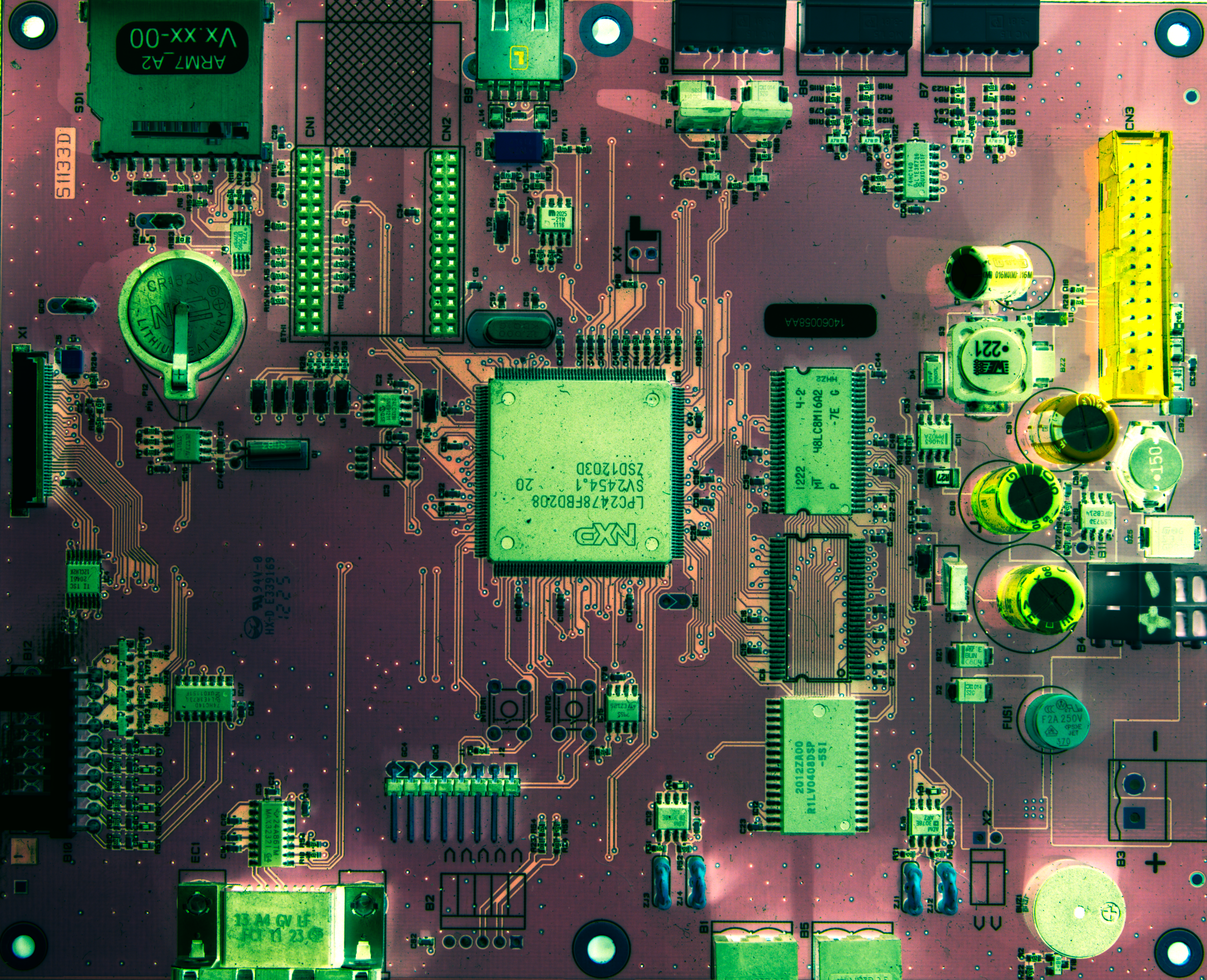
As an example, I’ll show you this PCB that I recently began exploring.

The result can be found below (click to view thefull resolution, but it’s ~30MB).
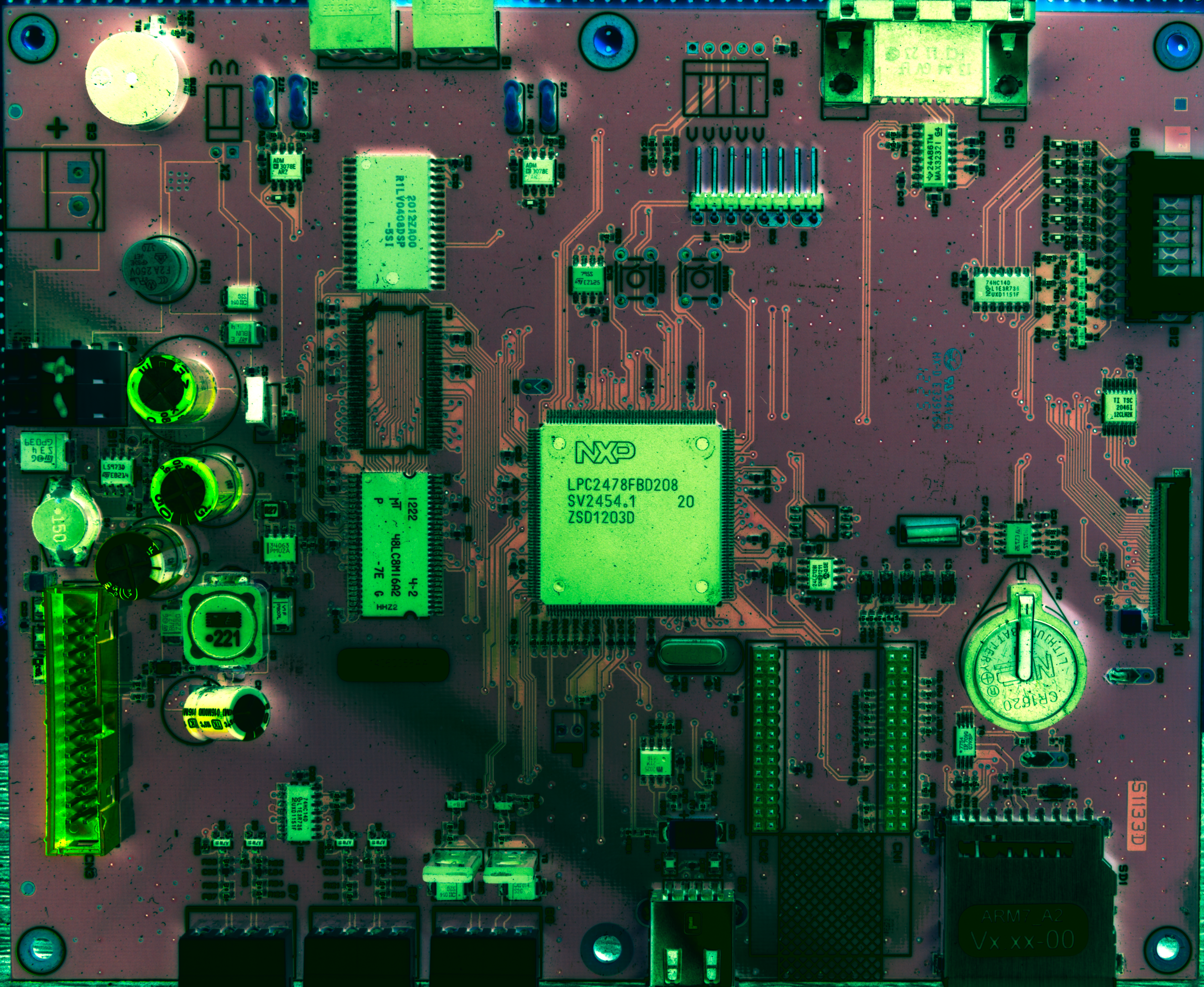
update
Another successful test with the CPL filter (~30 MB).
Same workflow with a RPI Zero (~15MB).
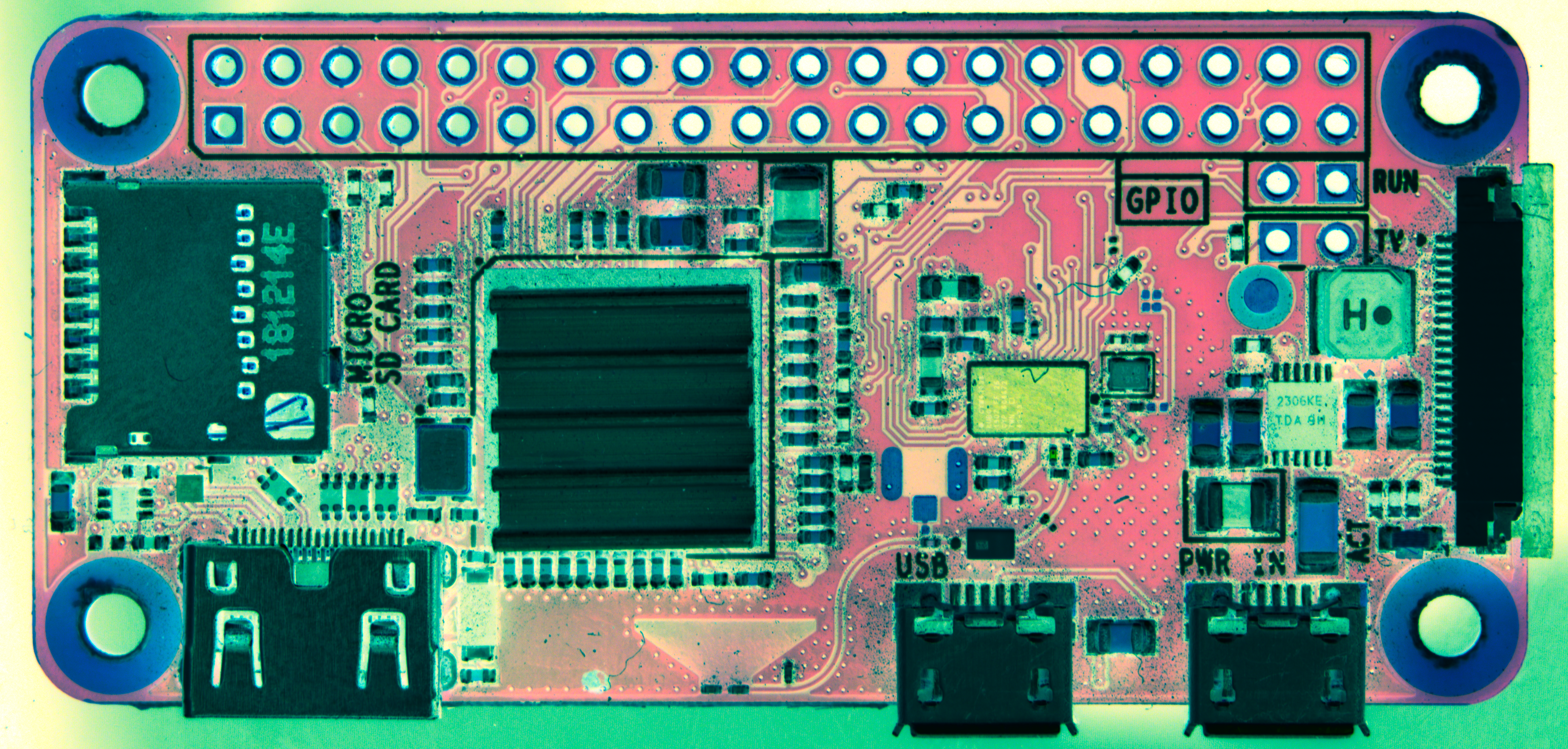
Some boards, like the Pi Zero, have chips with different colors (brillant metal or black), so it’s helpful to take multiple photos with various settings to capture all the details (test 2 and test 3.
That’s it for today!
As always, a big congratulations to all the contributors of these amazing tools, eg: RawTherapee and gPhoto2 — If you’re able, please consider supporting the open-source community through sponsorship.
^EOF